Mechanical Design
- Design Overview
- Frame Design
- Wrench Panel
- Bucket Panel
- Uncle Ed Panel
- Start Button Panel
- Bottom Panel
- Top Panel
- Structural Reinforcement
- 3D-Printed Part Files
Design Overview
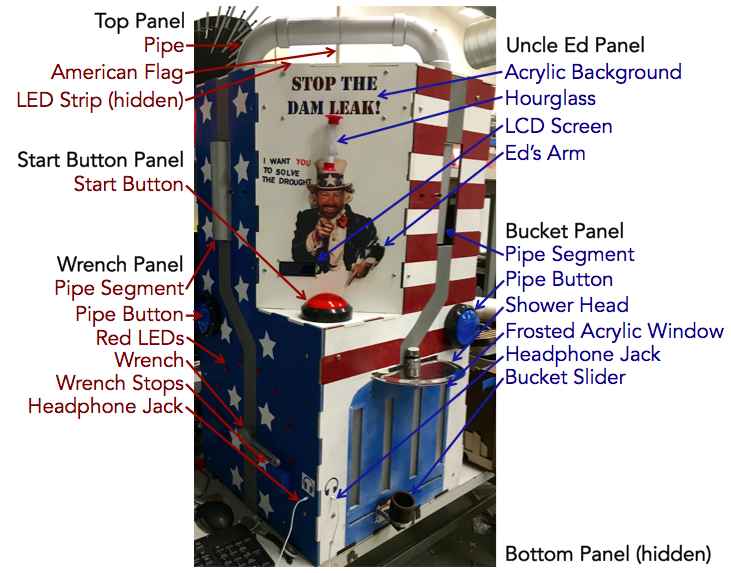
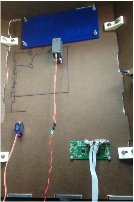
Our game was designed to have each player playing on one side, with a shared central display. Here's a photo of the design and the main parts:
Our game was designed to have each player playing on one side, with a shared central display. Here's a photo of the design and the main parts:
Frame Design
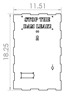
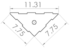
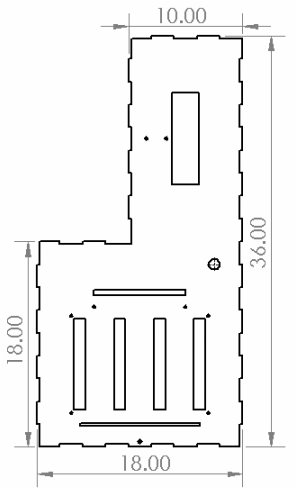
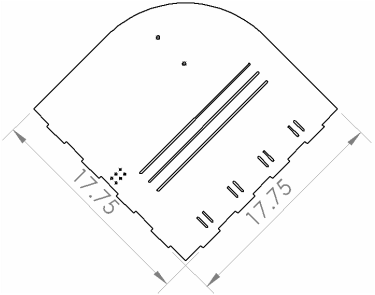
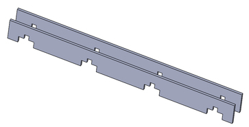
The external frame of our DAM was laser cut out of sheets of ¼" thick duron. We made the frame as 6 panels that fit into an 18"x18"x36" box, as shown here (all dimensions in inches):
The external frame of our DAM was laser cut out of sheets of ¼" thick duron. We made the frame as 6 panels that fit into an 18"x18"x36" box, as shown here (all dimensions in inches):
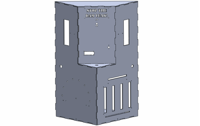
SOLIDWORKS Assembly of the Six Panels
Top Panel
|
Uncle Ed Panel
|
|
|
Wrench Panel
|
Start Button Panel
|
Bucket Panel
|
Bottom Panel
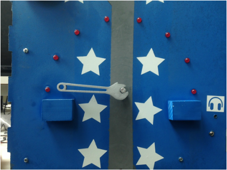
Wrench Panel
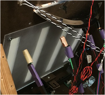
The wrench panel had a pipe segment, a pipe button, the wrench mechanism, two wrench stops, 8 red LEDs, and a headphone jack. We mounted the pipe segment by gluing it to a laser cut piece of duron and gluing and screwing the duron to the servo horn. We supported the servo using screws tightened down onto the panel and another laser cut duron piece. The assembly is shown here:
The wrench panel had a pipe segment, a pipe button, the wrench mechanism, two wrench stops, 8 red LEDs, and a headphone jack. We mounted the pipe segment by gluing it to a laser cut piece of duron and gluing and screwing the duron to the servo horn. We supported the servo using screws tightened down onto the panel and another laser cut duron piece. The assembly is shown here:
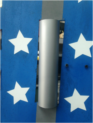
Front View of Pipe Mount on Wrench Panel
|
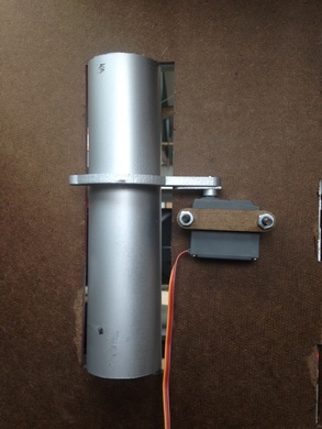
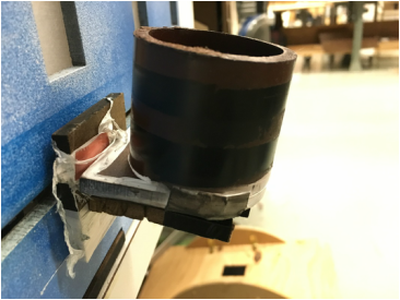
Back View of Pipe Mount on Bucket Panel
|
To mount the pipe button, we simply screwed it through the laser cut hole in the duron and tightened it down, as shown here:
Side View of Pipe Button Mount on Wrench Panel
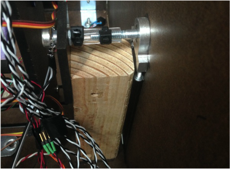
For the wrench mechanism, we 3D printed a wrench to fit a long hex bolt that fit through the laser cut hole on the wrench panel. On the backside, we glued a bearing to the panel and used a plastic tube to couple the hex bolt to a potentiometer. We mounted the potentiometer using a block of wood screwed into the bottom panel with a laser cut piece of duron on top. Additionally, on the front, we screwed in two blocks of wood to limit the range of motion of the wrench so that it did not reach the limits of the potentiometer. The mechanism is shown here:
Front View of Wrench Mechanism on Wrench Panel
|
Back View of Wrench - Potentiometer Coupling on Wrench Panel
|
To mount the LEDs and headphone jack, we simply glued them through an appropriately sized hole on the panel, as shown here:
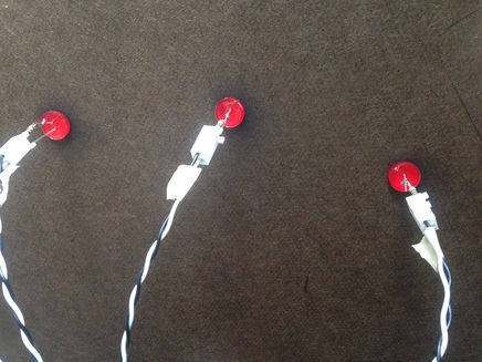
Back View of LED Mounts on Wrench Panel
|
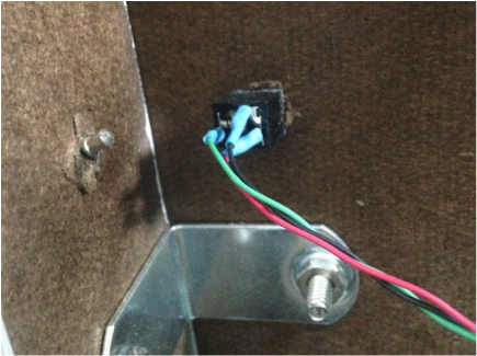
Back View of Headphone Jack Mount on Wrench Panel
|
Bucket Panel
The bucket panel had another pipe segment and pipe button, a shower head, a frosted acrylic window, the bucket slider mechanism, and another headphone jack. The shower head was mounted by letting it rest in a large hole laser cut in the panel and using a zip tie to fasten it through two small holes, as shown here:
The bucket panel had another pipe segment and pipe button, a shower head, a frosted acrylic window, the bucket slider mechanism, and another headphone jack. The shower head was mounted by letting it rest in a large hole laser cut in the panel and using a zip tie to fasten it through two small holes, as shown here:
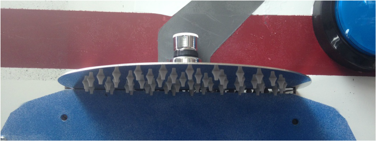
Front View of Shower Head Mount on Bucket Panel
The frosted acrylic window was created by sanding a sheet of clear acrylic and using nuts and bolts to fasten it to the panel using matching holes laser cut in the acrylic and the panel, as shown here:
Back View of Frosted Acrylic Window on Bucket Panel
The bucket slider mechanism was built by laser cutting a long, thin piece of duron (the slider) to fit through a slot laser cut in the panel, and having two laser cut pieces of duron bolted into the slider on top and bottom on the front and back side of the panel. Sandwiched between these pieces and the panel on front and back was another piece of duron wrapped in teflon tape to make it slippery. Additionally, a thin piece of cardboard (the flag) was glued to the bottom of the back of the slider to trip the coin sensors. The flag was guided using two laser cut duron rails glued to the coin sensors and glued down to the bottom panel. The mechanism is shown here:
Front View of Bucket Slider on Bucket Panel
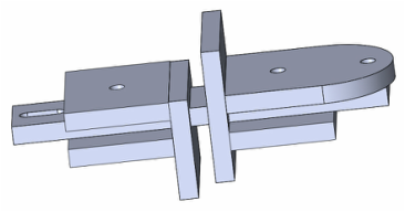
CAD for the Bucket Slider
|
Back View of Bucket Slider and Coin Sensor Mounts on Bottom Panel
CAD for Coin Sensor Mounts
|
The bucket slider ended up being the weakest link of our project, and it came loose as the game was played on the night of the presentations. This was most likely due to the fact that we used slots instead of holes on the slider to fasten the pieces of duron together. If we had more time, we would have made this part of the mechanical design more robust.
Uncle Ed Panel
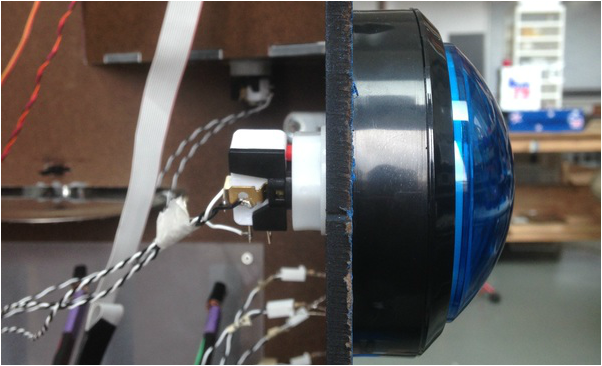
The Uncle Ed panel had another acrylic window, an hourglass and Ed's arm on servos, and the LCD screen. The acrylic window was laser cut and bolted into the panel the same way as the one on the bucket panel. In order to mount the hourglass, we had to extend the servo horn out from the panel surface so that the hourglass did not bump against the surface. We did this by gluing extra pieces between the servo horn and the hourglass. Uncle Ed's arm was mounted by gluing it to a servo horn. The servos and the LCD screen were bolted into the panel. The entire panel is shown here:
Uncle Ed Panel
The Uncle Ed panel had another acrylic window, an hourglass and Ed's arm on servos, and the LCD screen. The acrylic window was laser cut and bolted into the panel the same way as the one on the bucket panel. In order to mount the hourglass, we had to extend the servo horn out from the panel surface so that the hourglass did not bump against the surface. We did this by gluing extra pieces between the servo horn and the hourglass. Uncle Ed's arm was mounted by gluing it to a servo horn. The servos and the LCD screen were bolted into the panel. The entire panel is shown here:

Front View of Uncle Ed Panel
|
Back View of Uncle Ed Panel
|
Start Button Panel
The start button panel simply had the start button mounted on it just like the pipe buttons. It is shown here:
The start button panel simply had the start button mounted on it just like the pipe buttons. It is shown here:
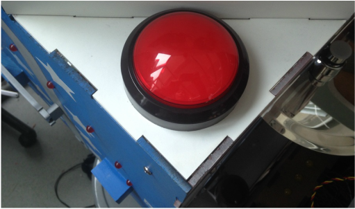
Top View of Start Button Panel
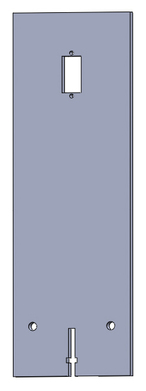
Bottom Panel
The bottom panel had mounts for the potentiometer support and coin sensors as described above. It also had holes to mount the circuit board and slots to mount the bucket LED servos. The circuit board was mounted by sticking two breadboards to a piece of duron and bolting the duron piece through two holes in the bottom panel, as shown here:
The bottom panel had mounts for the potentiometer support and coin sensors as described above. It also had holes to mount the circuit board and slots to mount the bucket LED servos. The circuit board was mounted by sticking two breadboards to a piece of duron and bolting the duron piece through two holes in the bottom panel, as shown here:
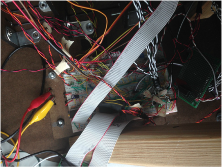
Top View of Circuit Board Mount on Bottom Panel
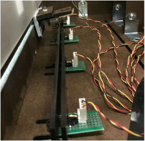
Additionally, for each of the four LED-servo combinations, a piece of duron was laser cut and bolted through the bottom of the bottom panel. Brackets were used to stabilize each duron piece. At the top of each duron piece, a servo was bolted in, and a laser cut duron piece was glued onto the servo horn, with a blue LED taped to the end. The mechanism is shown here:
Back View of LED Servo Mounts on Bottom Panel
|
CAD for One of Water LED Servo Supports
|
For a video of the bucket LED servos working, click here.
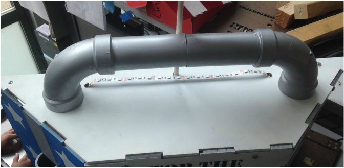
Top Panel
The top panel had purely decorative elements: an American flag glued in though a hole, a pipe glued onto the surface, and an LED strip taped on and secured through a pair of holes. The top panel is shown here:
The top panel had purely decorative elements: an American flag glued in though a hole, a pipe glued onto the surface, and an LED strip taped on and secured through a pair of holes. The top panel is shown here:
Top View of Top Panel
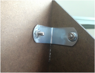
Structural Reinforcement
To reinforce the structure, we bracketed all edges by bolting each panel to several brackets at the corners. Since 135 degree angle brackets were difficult to find, we 3D printed our own. The brackets are shown here:
To reinforce the structure, we bracketed all edges by bolting each panel to several brackets at the corners. Since 135 degree angle brackets were difficult to find, we 3D printed our own. The brackets are shown here:
90 Degree Bracket Between Top and Bucket Panel
|
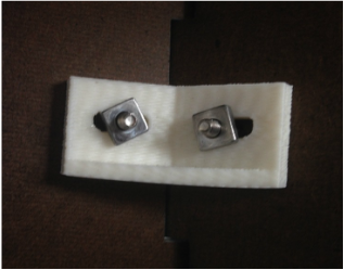
3D Printed 135 Degree Bracket Between Uncle Ed and Wrench Panel
|
Since the bucket and wrench panels had to take a lot of force behind the two pipe buttons, we added two angled pieces of wood screwed between these two panels and the bottom panel, as shown here:
View of Wooden Support Between Bottom and Wrench Panels
3D-Printed Part Files
|
| ||||
